
The two binary numbers to be added serially are stored in two shift registers (using two 74164, 8-bit serial-in, parallel-out shift registers). shows the block diagram design of a serial adder. Randomness? Does the output repeat after 15 pulses?įig. The clock and record the output in a table. SW1 to logic 0 as this will release the control input. Set the initial state of the shift register to 0001 by setting the switch The IC 7486 provides theĮxclusive-OR needed in the circuit. Random output (repeats every 2 n–1 bits, where n is the number ofįlip-flops used in the shift register).

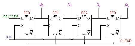
This binary sequence generator will display a Now use the above circuit to build a pseudo-random binary sequence generatorĪs shown in Fig. More logic 1 to be shifted into the shift register. Push the pulser button several times to allow SW2 being at logic 1 clears all flip-flops. Connect L1–L4 to four LEDs (with current-limiting resistors), SW1 Use two 7474 dual flip-flops to connect a serial-in, parallel-out shift Students are expected to understand various data handling methods in shift

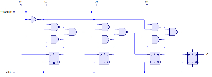
A serial adder will be built in this experiment as an example. Therefore, serial computation is slower, but it has the advantage of requiring less hardware and wiring. Compared to parallel computation, where all bits in a word are processed at the same cycle, serial computation process words in one bit per cycle. One of the important applications of shift register circuits is in serial computation. Shift registers are classified according to three basic considerations: their method of data handling (serial-in serial-out, serial-in parallel-out, and parallel-in serial-out), their direction of data movement (shift right, shift left, and bidirectional), and their bit length. The output of a shift register can be observed one bit at a time at the serial output, but some shift registers also have parallel outputs for observing all n bits at once. Some shift registers also have parallel inputs that can be used to load all n bits in one clock cycle. One way to load n bits of data into the flip-flop chain is to load the data one bit each clock cycle using the serial input.


 0 kommentar(er)
